

Industrial CNC solution
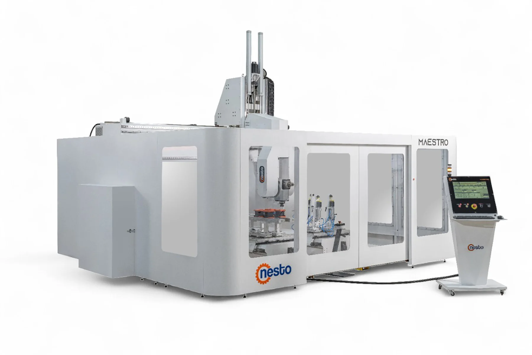
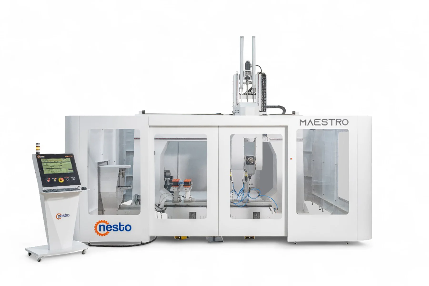
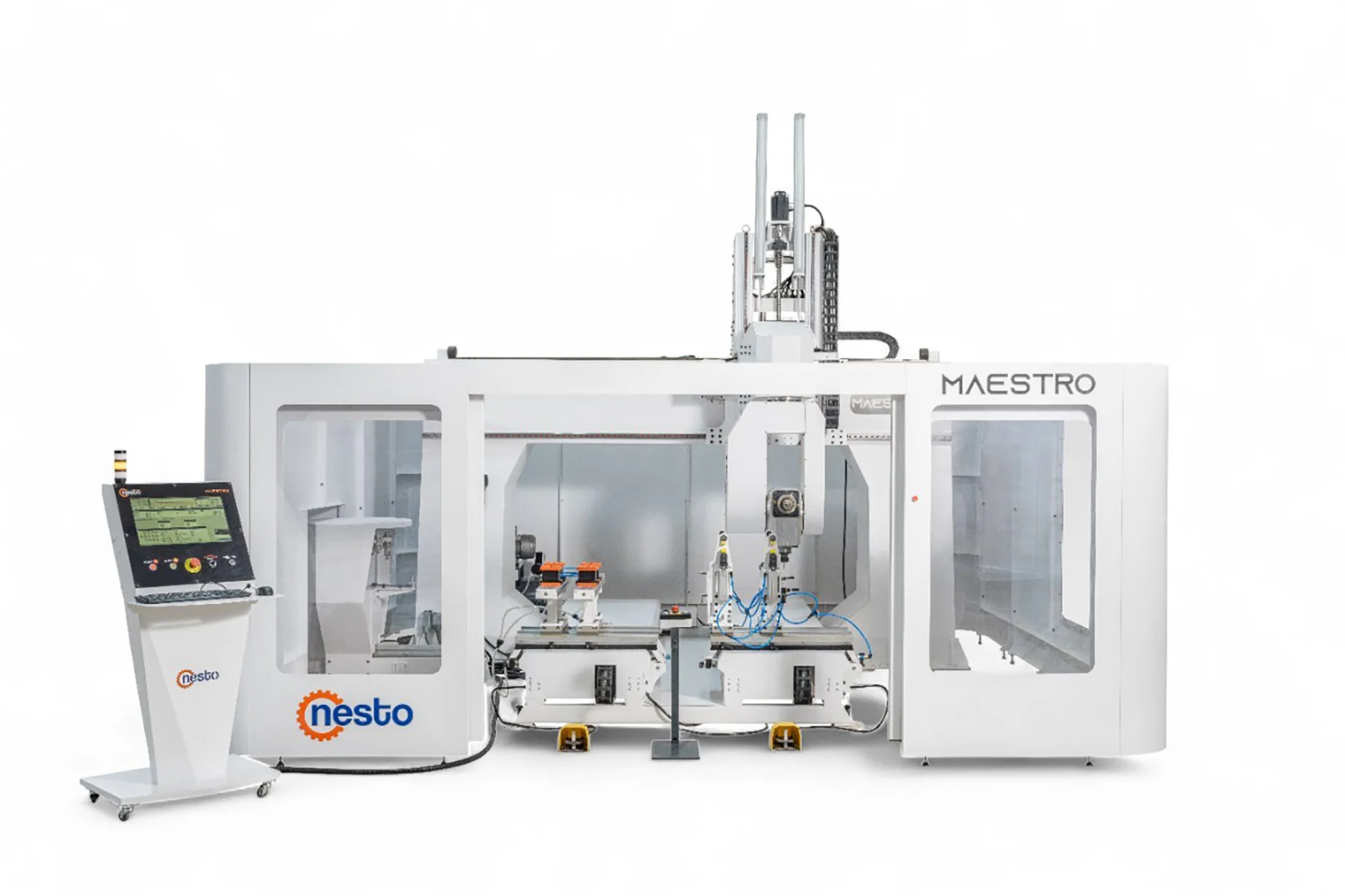
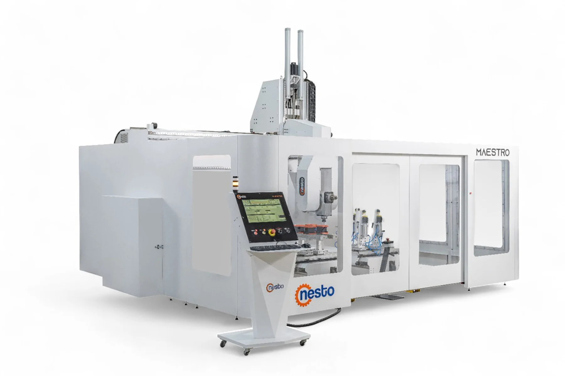
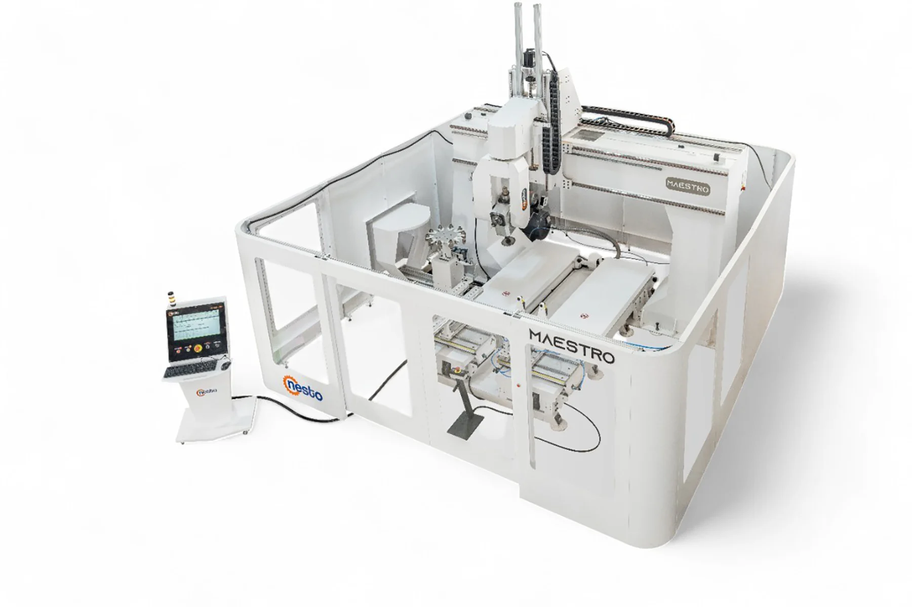
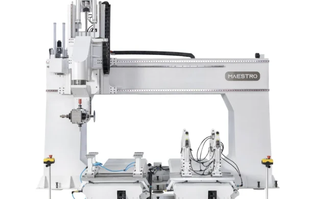
Maestro T3 5 Axis Cnc Machining Center
Configure the right machine for your production
Share your part, material and capacity requirements. Our team will help you determine the suitable machine configuration.
- Application-focused configuration
- Technical sales guidance
- Installation and service planning
You can include part drawings and production expectations in the quote form.
General Features and Production Capabilities

Three-spindle machining on one platform
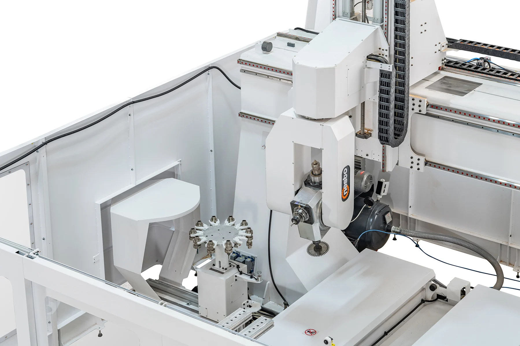
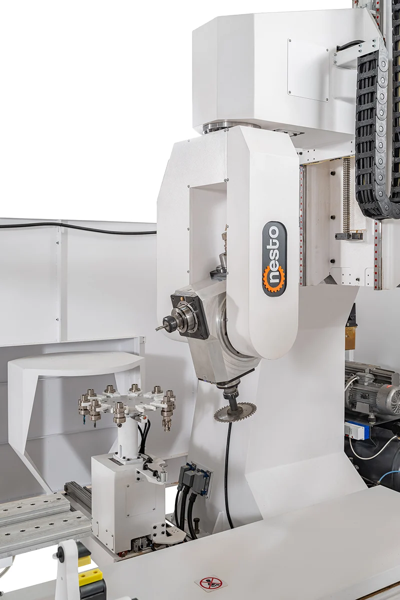
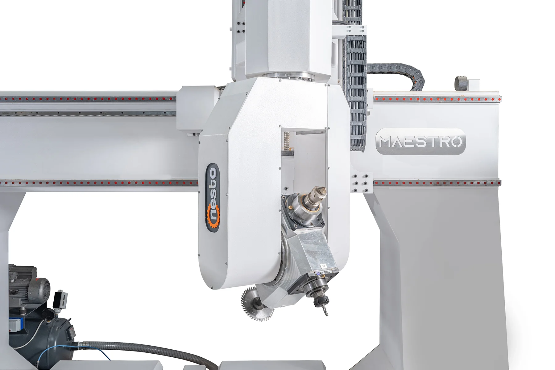
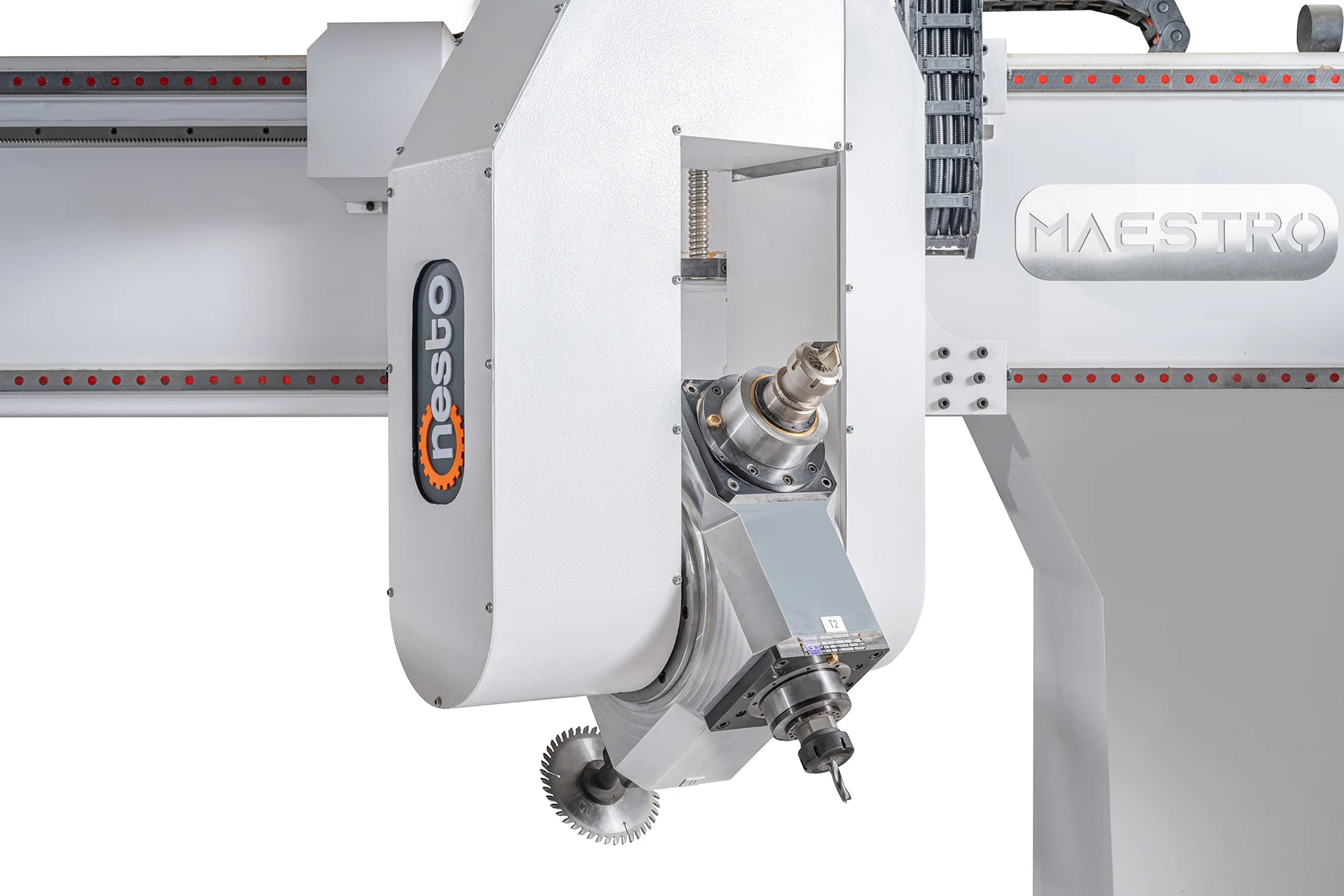
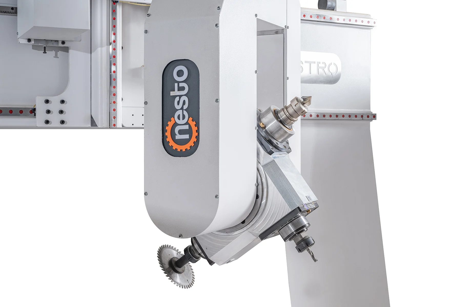
One 10 kW ATC spindle and two 7.5 kW MTC spindles keep different tool directions and machining tasks available for complex solid-wood components.

Broad three-dimensional working envelope
The 1,950 mm X, 1,250 mm Y and 1,000 mm Z travels provide room for multi-face milling, drilling, profiling and joinery operations on solid-wood furniture parts.
- X 1,950 mm
- Y 1,250 mm
- Z 1,000 mm

Servo-driven precision movement
Servo motors on all axes support controlled acceleration, repeatable positioning and coordinated movement across the full machining envelope.

Rigid monoblock chassis
The reinforced, vibration-resistant chassis forms a stable base for high-speed spindle work and coordinated multi-axis motion.

Flexible workholding for solid-wood components
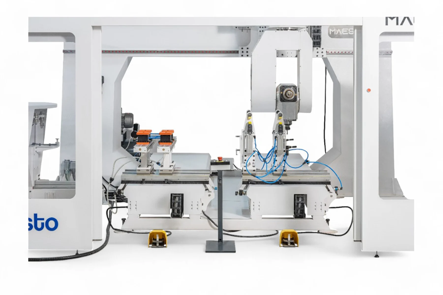
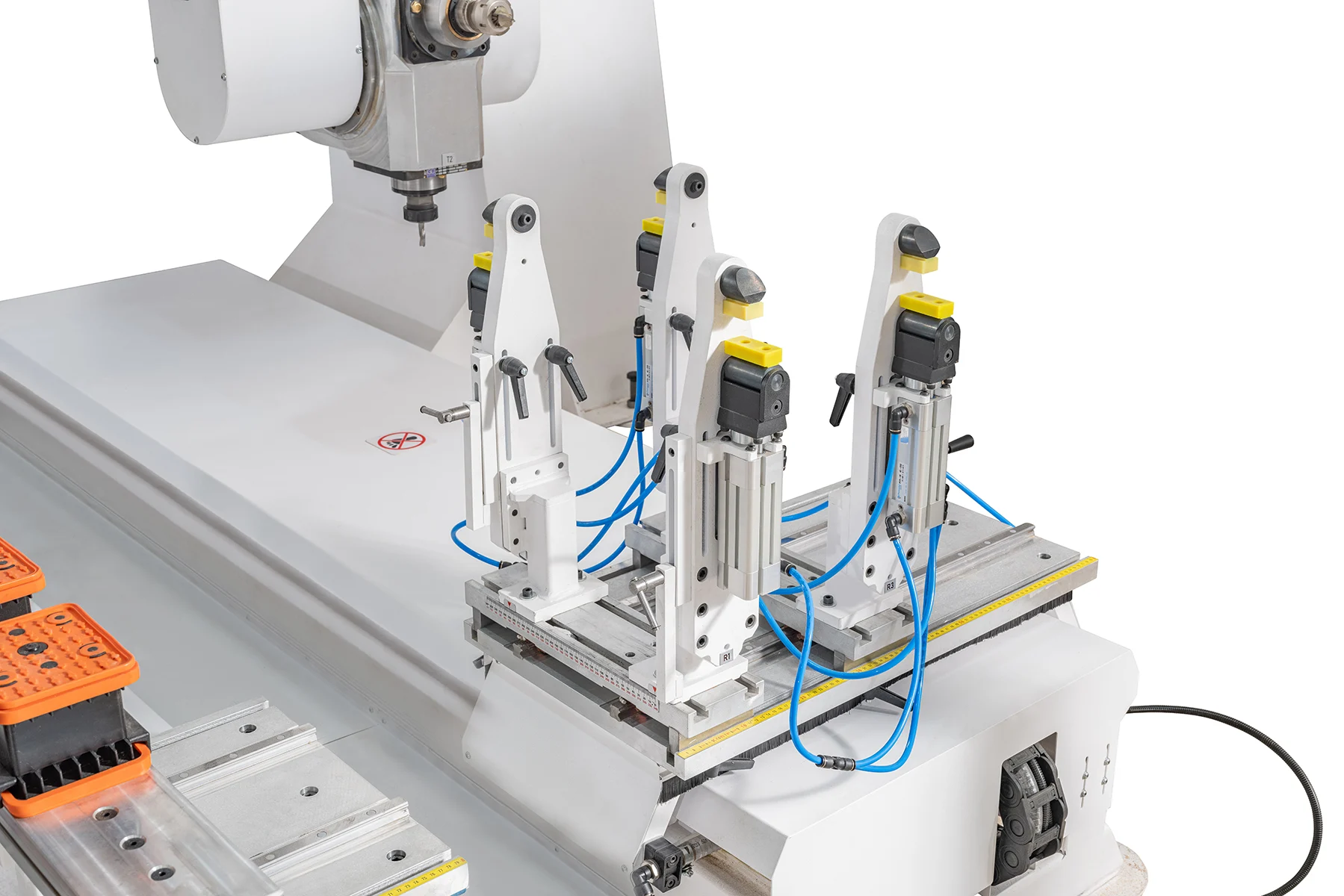
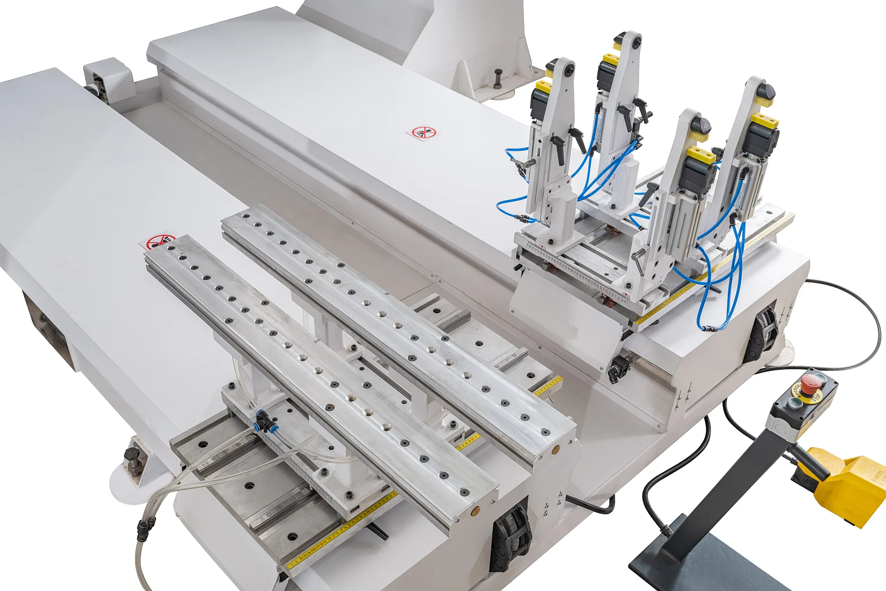
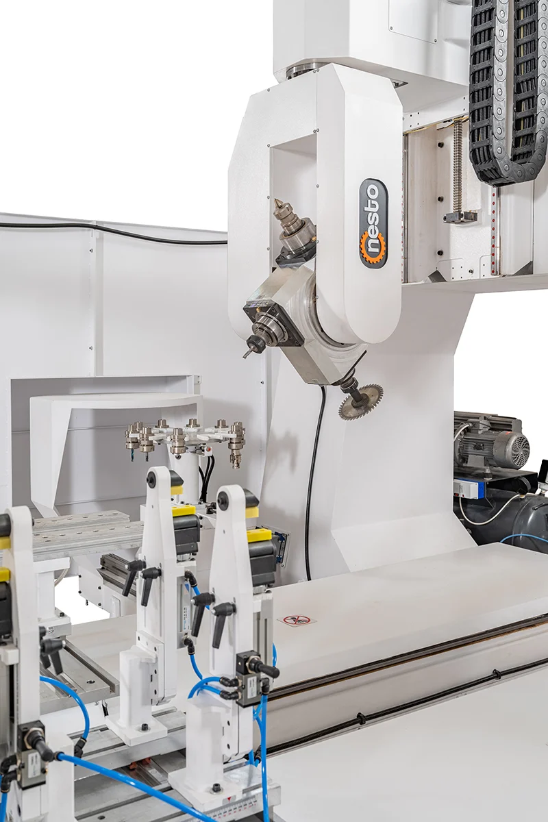
Adjustable supports and pneumatic clamps help position different part geometries while preserving tool access for multi-sided machining.

Automatic and manual tool-change combination
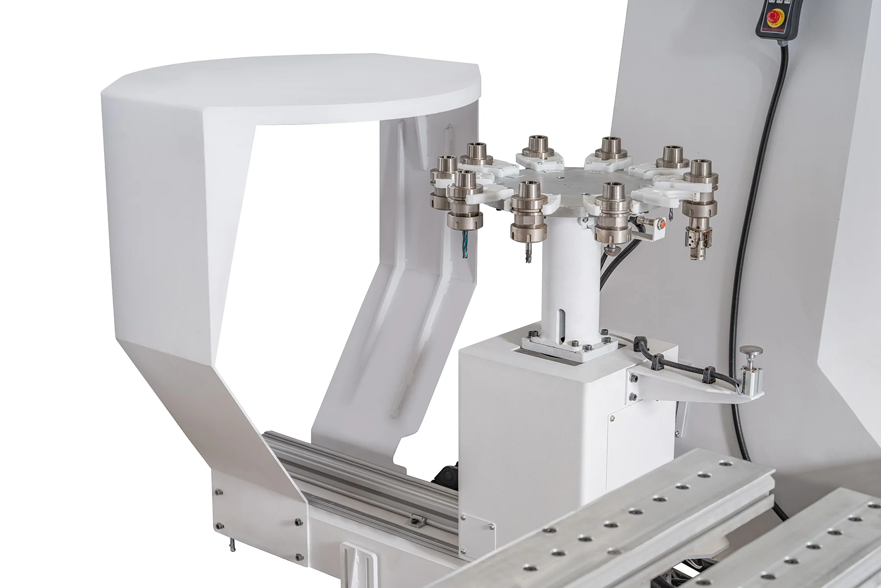
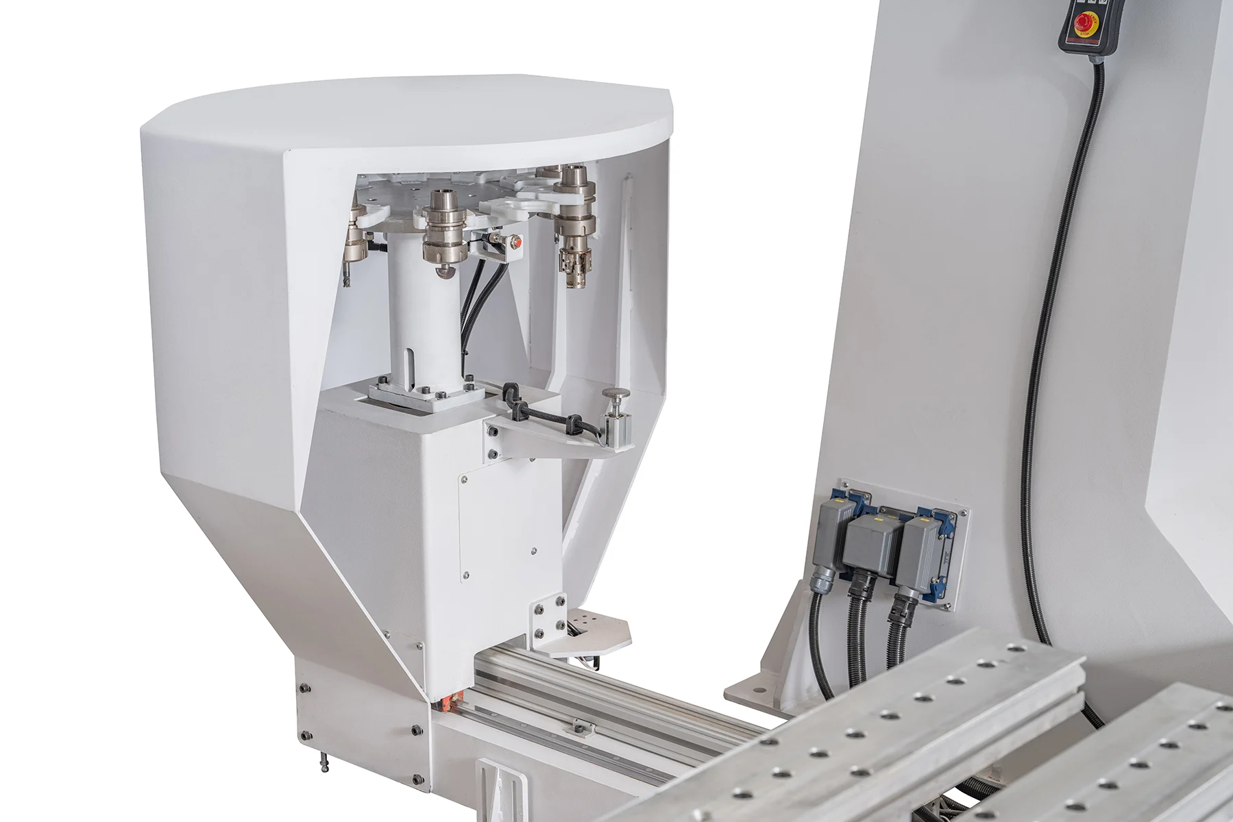
The ATC spindle supports programmed tool changes, while the two MTC spindles can remain prepared for selected complementary operations.

Remote visibility and production reporting
The operator station brings together remote connection, advanced reporting and 3D preview functions for clearer production follow-up.

CAD/CAM simulation and optimizer workflow
Models can be programmed and simulated in 3D before machining. STL, DWG, DXF and IGES data can enter the workflow, while optimization helps order operations efficiently.
Technical Specifications
| Specification | Maestro T3 |
|---|---|
| X-axis travel | 1,950 mm76.77 in |
| Y-axis travel | 1,250 mm49.21 in |
| Z-axis travel | 1,000 mm39.37 in |
| Automatic tool-change spindle | 1 × Colombo · 10 kW (13.6 HP) · ATC |
| Manual tool-change spindles | 2 × Colombo · 7.5 kW (10 HP) · MTC |
| Spindle speed | 24,000 rpm |
| Spindle bearings | Ceramic bearings |
| Axis drive | Servo motors on all axes |
| Chassis construction | Reinforced · vibration-resistant · rigid monoblock |
| Control functions | Remote connection · advanced reporting · 3D preview |
| CAD/CAM functions | Model programming · 3D simulation · production optimization |
| Supported data workflow | STL · DWG · DXF · IGES |
| Dimensions with safety enclosure (L × W × H) | 4,800 × 4,800 × 3,900 mm188.98 × 188.98 × 153.54 in |
| Dimensions without safety enclosure (L × W × H) | 4,075 × 3,400 × 3,900 mm160.43 × 133.86 × 153.54 in |
Standard Main Equipment
10 kW Colombo ATC spindle
The automatic tool-change spindle operates at 24,000 rpm with ceramic bearings for programmed multi-operation cycles.
Two 7.5 kW Colombo MTC spindles
Two manual tool-change spindle units operate at 24,000 rpm and can be prepared for complementary tool directions and operations.
Industrial operator control
The mobile operator console combines machine control, remote connection, reporting and 3D preview functions.
Servo-driven axis group
Servo motors drive every axis for coordinated acceleration and repeatable positioning.

CAD/CAM programming and 3D simulation
The digital workflow supports model preparation, compatible file transfer and simulation before the production program is released.
Production optimizer
The optimizer helps arrange machining steps to reduce unnecessary transitions and support a more efficient cycle.
Adjustable workholding platform
Movable supports and pneumatic clamps adapt the fixture layout to different solid-wood part geometries.
Enclosure Configurations
Fully enclosed configuration
The documented enclosed layout measures 4,800 × 4,800 × 3,900 mm. Final service, extraction and material-handling clearances are planned separately.
- 4,800 × 4,800 × 3,900 mm
Open configuration without enclosure
The documented open layout measures 4,075 × 3,400 × 3,900 mm. The required perimeter safety system is determined in the final installation plan.
- 4,075 × 3,400 × 3,900 mm
Typical applications
- Multi-face solid-wood machining
- Complex furniture components
- Chair legs
- Table legs
- Joinery components
Model selection
Frequently asked questions
Which parts can Maestro T3 machine?
Maestro T3 is designed for multi-sided solid-wood furniture components such as chair and table elements, structural joinery parts, frames, curved or profiled components and complex decorative pieces. Final suitability is evaluated from the 3D model, raw stock, workholding plan and required tool access.
What is the Maestro T3 working envelope?
The documented axis travels are 1,950 mm in X, 1,250 mm in Y and 1,000 mm in Z, equivalent to approximately 76.77 × 49.21 × 39.37 inches. Actual usable space depends on the fixture, tool orientation and collision-clearance plan.
How does the three-spindle architecture work?
The machine combines one 10 kW Colombo spindle with automatic tool change and two 7.5 kW Colombo spindles with manual tool change. All three run at up to 24,000 rpm with ceramic bearings. The arrangement keeps selected tools and machining directions available during a coordinated program.
What do CAD/CAM, 3D simulation and optimization provide?
The workflow supports model programming, 3D simulation before machining, supported STL, DWG, DXF and IGES data transfer and optimized operation sequencing. The final program is verified against the part geometry, fixtures and tool set.
Which control and production-follow-up functions are available?
The operator station combines machine control with remote connection, advanced reporting and 3D preview. These functions support clearer production follow-up and remote diagnostic communication when required.
What are the enclosed and open installation dimensions?
The documented enclosed layout is 4,800 × 4,800 × 3,900 mm (188.98 × 188.98 × 153.54 in). The open layout is 4,075 × 3,400 × 3,900 mm (160.43 × 133.86 × 153.54 in). Service access, extraction, electrical infrastructure, material handling and perimeter safety space must be added to the final plan.
Which part data should be shared for a production evaluation?
Share the part drawing or 3D model, wood species, raw-stock dimensions, finished geometry, faces and operations to be machined, expected daily quantity, surface target and preferred workholding method. A physical sample is useful when geometry or wood behaviour requires validation.
Reviews
There are no reviews yet.